Side-Quest: Reshelling a Nintendo DS
My first steps into tinkering
Introduction
I recently finished my first, small tinkering project. A while ago, I fell into the video game consoles modding rabbit hole (both hardware and software). I had been thinking of doing one simple mod myself, for a console I had nostalgia for.
Even though I did not grow up with one, I always thought the Nintendo DS (especially the Lite model) looked really cool. Nowadays, it’s easy to pick up a used one for £30. The hinge on the system do not age well though, and they easily break. Units with a broken hinge are usually sold ‘for parts’ on eBay for a discounted price.
Fixing a broken hinge can be done by changing the shell of the console, e.g. by reshelling it. While it’s not a straightforward task, it is an accessible one.
So I ended up getting a Nintendo DS with a broken hinge for £15 and a really cool SNES-themed shell from extremeRate for £26. It sounds expensive, but I found the quality of the shell and pieces really nice to work with, so it was definitely worth it in my opinion.
I followed this YouTube video as a guide for the shell replacement. It is perfectly paced and easy to follow.
This blog post is not intended to be a guide. I simply wanted to show off and use this as a log of the project for myself.
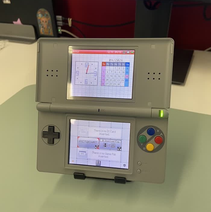
Starting Point
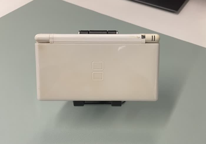
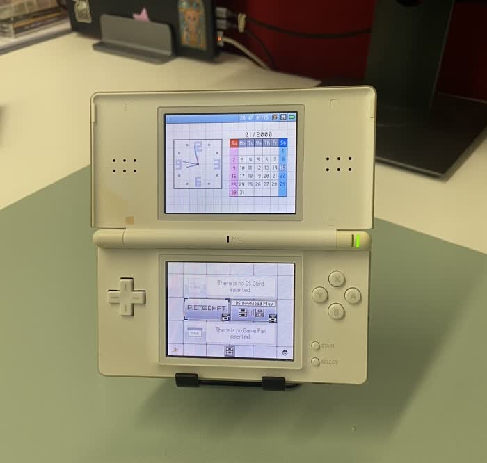
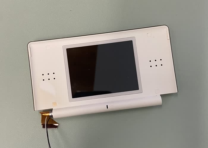
This is what the DS looked before any modifications were done to it. It had yellowed with age, looked quite dirty, and we can see the broken hinge (first pic, top right).
A reshelling process is split into two parts: disassembly, where we extract all the components from the old shell, and reassembly, where we put the components in the new shell.
Disassembly
Disassembly was surprisingly (relatively) tricky, and you can’t just yank everything out. there are some ribbon cables to be aware of!
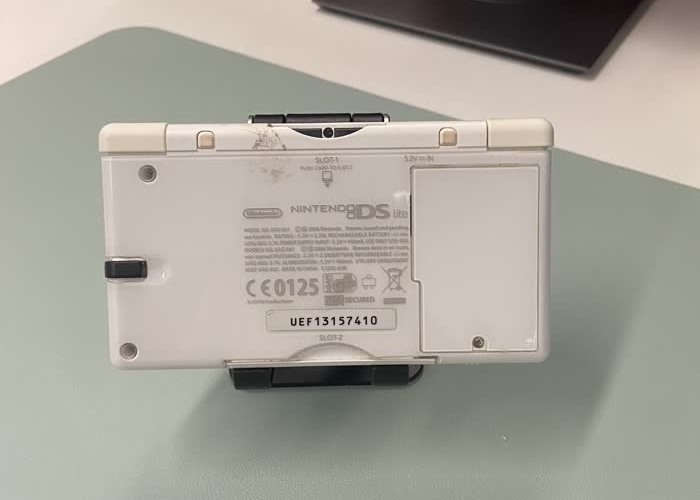
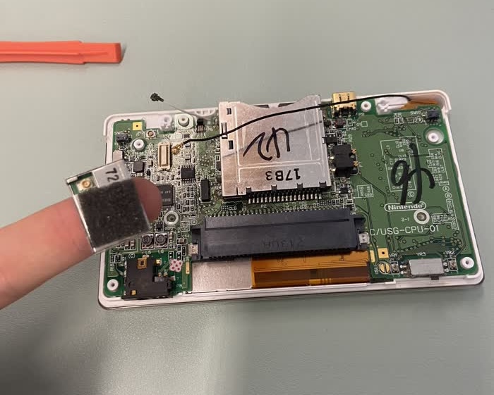
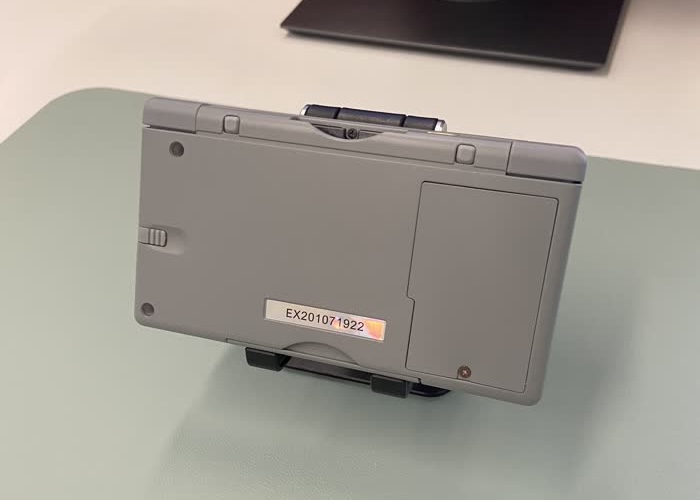
First step is to remove the back cover. One of the shoulder buttons came out, but that’s no biggie, as long as the spring is still here. I was quite surprised to see these numbers on the motherboard and cartridge slot. Maybe the unit had been opened before?
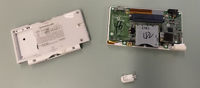
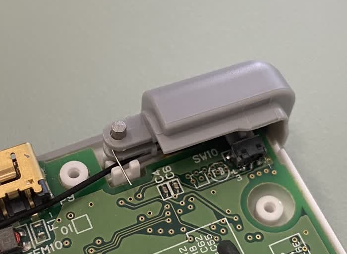
Next, we take the Wi-Fi chip out (what’s on my finger), and pull the antenna’s cable (black) from under the cartridge slot.
After disconnecting the ribbon cables of both screens, we can safely extract the motherboard from the bottom shell.
Now that the top half is disconnected, we remove the screws hidden behind those little rubber squares around the screen (one of them is yellowed, bottom left), and remove its back cover by simply sliding it out:
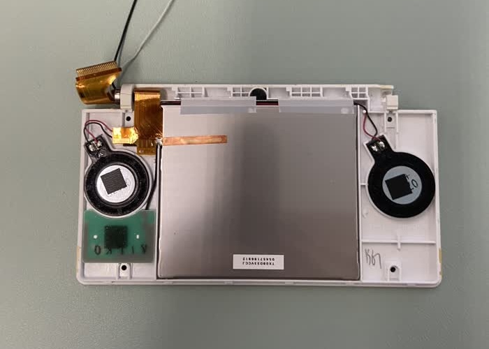
Next, we extract the screen from the shell by simply pushing it out. It is only stuck to the shell using double-sided tape.
The disassembly is done now. The old shell can be put to the side for now.
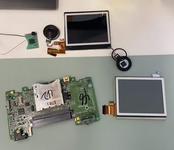
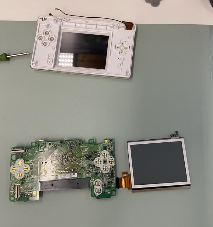
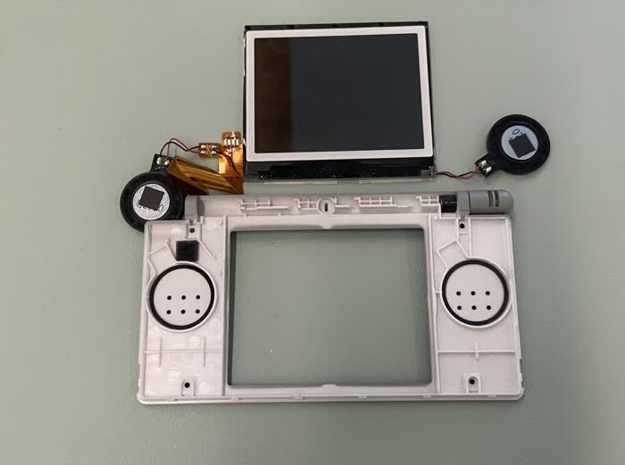
Legend:
- Top Left: Wi-Fi Antenna + Microphone
- Top: Top Screen + Both speakers
- Bottom Left: Motherboard
- Bottom Right: Bottom Screen
Reassembly
We can now start putting everything back together in the new shell.
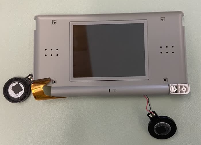
This next step is probably the trickiest of the entire process. The top screen is actually covered by a plastic transparent protector. You need to peel it off, place the ‘bare’ screen in the plastic case, using double-ended tape to make it stick to it, and then place the new screen protector. While this was relatively easy, it was a bit nerve-racking, as I really wanted the screen to be straight and prevent dust from getting between the screen and the protector. I ended up not taking pictures of the process. In the end, the screen was placed correctly. The backplate of the top half of the case isn’t screwed in yet, so the speakers are still hanging on the side.
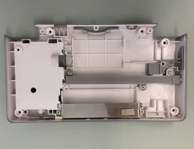
The little white knob on the bottom right is the part of hinge that is responsible for making it click.
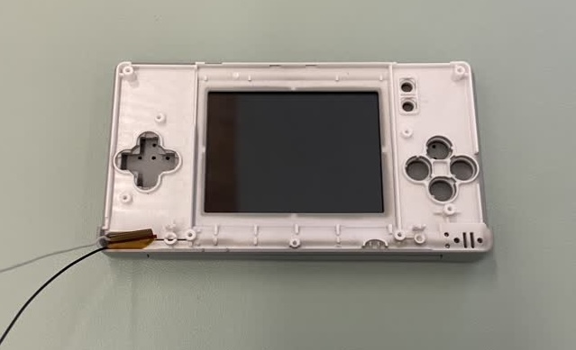
Now we thread the top screen’s ribbon cable through the front plate of the bottom case. What we see in the next picture is the top half of the shell, on which lays the user-facing side of the bottom case, inside out. The white and black cables are for the Wi-Fi antenna and microphone respectively.
From this point on, I would say this is the easier part. The next step is to set the D-Pad and A/B/X/Y buttons in the shell. Since each button has a different colour, the shell set came with an entire set of button for each colour. This means that I have basically all the buttons I would need to do another similar mod.
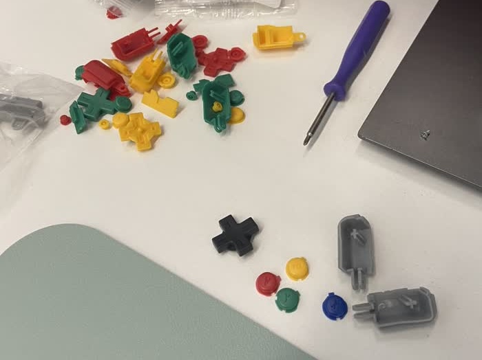
Then, we move on to the shoulder buttons. Putting them in can be a bit tricky, as you need to insert the spring with the correct orientation, and make sure the side that stick out sits in the little white indent in the shell.
One final step before we screw the back cover back is to insert the stylus holder (grey horizontal piece) and the GBA slot protector (metal piece at the bottom).
Screwing everything back together is straightforward. There aren’t that many screws, and they can easily be differentiated.
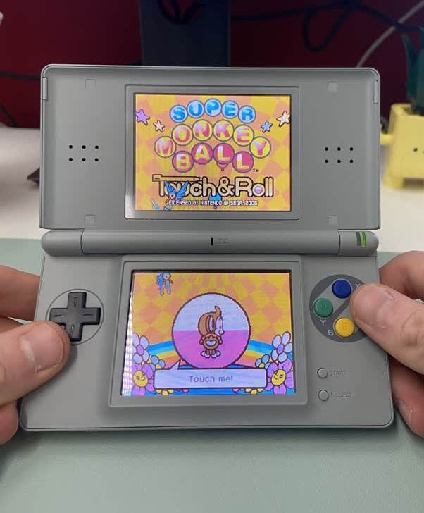
End Result
This is what the result looks like:
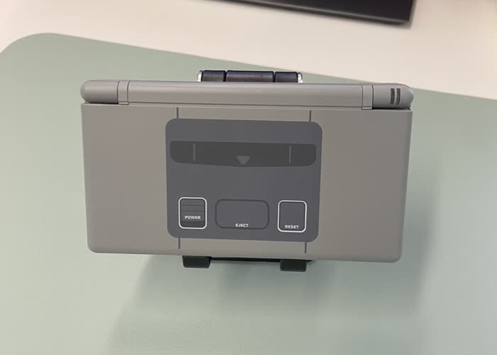
The buttons look really nice! I find the back side a bit bland however, without the usual copyright text etc.
Conclusion
This was a very fun and relatively stress-free project. It took me around 90 minutes. The video linked in the introduction really helped though!
Because of the DS’ small size, I was worried about the parts being easy to lose/break. Thankfully, everything turned out fine!
I will probably do another one of this in the near future, something more advanced or on a home console!
Notes for the future
- Have a pair of tweezers. They make removing the rubber pieces easier.
- Prefer re-using the screws from the DS instead of using the ones provided with the new shell, as they tend to strip more easily
- While the new membrane for the A/B/X/Y buttons feel really nice, that’s not the case for the D-Pad. I think I should have kept the old one since it was in good shape.